назад Оглавление Раздел документация вперед
страница - 0
GV-Data Capture V2 Users Manual
 2005/06 Before attempting to connect or operate this product, please read these instructions carefully and save this manual for future use.
Table of Contents Introduction 1 Unpacking 1 System Requirements 1 GV-Data Capture Overview 2 POS System Connection .................................. 3 DB9 Interface ............................................. 3 DB25 Interface ............................................ 4 System Configuration ...................................... 5 Cash Register Connection 7 DB9 Interface ............................................. 7 DB25 Interface ............................................ 8 System Configuration ...................................... 8 Extending Distance 9 Troubleshooting ............................................ 10 Display errors in transaction data 10 Transaction events did not stop properly 10 Connecting more than 2 POS systems/cash registers 13 Display transaction items did not match those entered at the POS system/cash register 13 Specifications 15 Introduction A POS system may be integrated to a GV-system through the GV-Data Capture box. Through the integration, you can investigate a transaction with transaction data overlaying on video footage, by either live viewing or playing back. Unpacking 1 x GV-Data Capture V2 box 1 x DB9 RS-232 cable (1.8 meters) 1 x DB9 RS-232 cable (3 meters) 1 x DB25 RS-232 cable (1.8 meters) 1 x Power Adaptor DC 5V 1 x DB9 Male to DB9 Male (Gender Changer) No. 4 1 x DB9 Female to DB9 Female (Gender Changer) No. 5 2 x Wall Hook System Requirements Version 6.0.2.0 or above IMPORTANT: The GV-Data Capture V2 is exclusively designed to support serial POS systems. For graphic mode or parallel POS systems, please refer to other documentation on our website: http: www.geovision.com.tw/002/en/FAQ/pos/FAQ-pos-Q2-3-082004.php
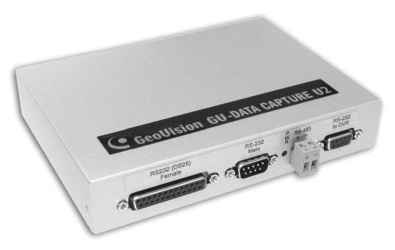
GV-Data Capture Overview The GV-Data Capture is a device that links a GV-System to an electronic POS system. It is designed to be installed between the GV-System and the POS system through PC COM ports. RS-232 DB25 Female RS-232 DB9 P „„.,,,- RS-232 Male W RS-485 to DVR . ;-v R + - ;- :<§> yv.v.v..v.v.vy Щ (®Of ° ЩШШр Front Panel DC IN RS-232 DB9 5V SW1 SW2 SW3 Female RS-232 DB25 Male Rear Panel | On: Debug Mode Off: Net Mode (Default) | щ нд On Off | | On: DB9 Mode (Default) Off: DB25 Mode | On Off | | On: Crossover Off: Non-crossover (Default) | On Off |
Note: Depending on your POS system/cash register output interface, find out RS-232 DB25 Male, DB25 Female, DB9 Male or DB9 Female on GV-Data Capture for connection. 2. If your POS system/cash register is using the DB25 interface, set DIP switch SW2 to OFF; otherwise keep the default setting. 3. If the cable, connecting your POS system/cash register to GV-Data Capture, is crossover, set DIP switch SW3 to ON; otherwise keep the default setting. 4. RJ-45 module installed in GV-Data Capture is optional. POS System Connection POS systems could come in different forms. In this manual, POS systems are referred to those with receipt printers externally connected. It is also important to identify the interface on your POS system used to connect a receipt printer to the POS system. It should be either DB9 or DB25 interface. Following will introduce the two Interface connections. DB9 Interface For the diagram below, we use a POS system using a DB9-DB25 cable for example. Depending on the POS system interface, find out the DB9 Female or DB9 Male connector on the GV-Data Capture for connection. ► POS system using a DB9-DB25 cable Female / Male DB9 Male / Female
 POS System

 GV-System DB9 Female DB25 DB9 Female / Male DB9 Male Male / Female [3> RS-232 Printer The RS-232 cables (1) 0 are supplied with the GV-Data Capture box. The RS-232 cable (3 is supplied with the POS system. The physical distance between the POS system and GV-System should be less than 10 meters (32 ft).
содержание:
[стр.Начало] [стр.1] [стр.2]
|

